
The Calculation Summary is the key to understanding how and if the numbers work in your lighting layout. Understanding each section can be the difference in whether you:
meeting code requirements, instill buying confidence in your client, save back-and-forth time with the electrical engineer, or build a positive reputation for your company as one that is efficient and knowledgeable. The following provides a quick understanding of what each column represents and how it is used within the lighting community.
LABEL
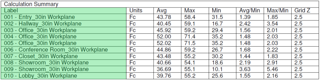
The LABEL shows both a general description and a calculation plane criteria.
The description may be the room name, a surface of the room like a wall, ceiling, or floor, or the surface of an object such as a table, countertop, or painting.
The calculation plane criteria describes the location of the calculation in reference to the surface or distance from the floor. By default, a work-plane is generally considered 30 inches above the floor, but this can be adjusted to any height including zero.
UNITS
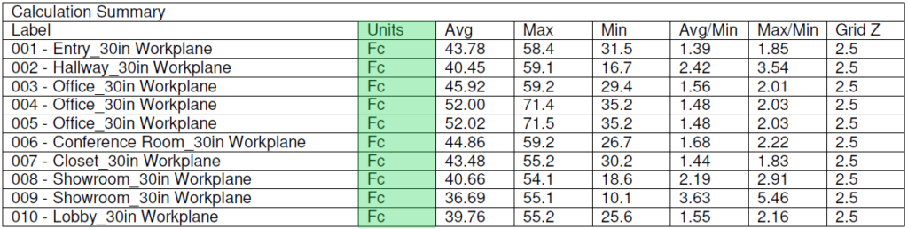
The UNIT of measure for calculations can either be in Foot-Candles (FC) or Lux. The standard in North America is the foot-candle.
AVG - AVERAGE
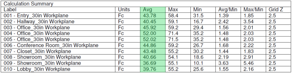
The AVERAGE light level is a general overview of the calculation plane, determined automatically by adding all of the individual calc-points together and then dividing by the total number of points within the plane. It is a number often used in codes as a standard light level to meet.
MAX - MAXIMUM
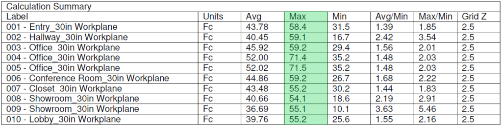
The MAXIMUM light level is the brightest point on the calculation plane. It is often the closest point to the light source, but because light is additive, it could also be found where several light sources intersect.
MIN - MINIMUM

The MINIMUM light level is the darkest area within the calculation plane. It is often found furthest from the light source, but can also be caused by an obstruction built within the 3D model.
AVG/MIN & MAX/MIN (Uniformity)

The AVG/MIN and the MAX/MIN are also known as Uniformity Ratios. They are mathematical formulas: Average divided by Minimum (Avg/Min) and Maximum divided by Minimum (Max/Min), where perfect uniformity is equal to 1.
Grid Z
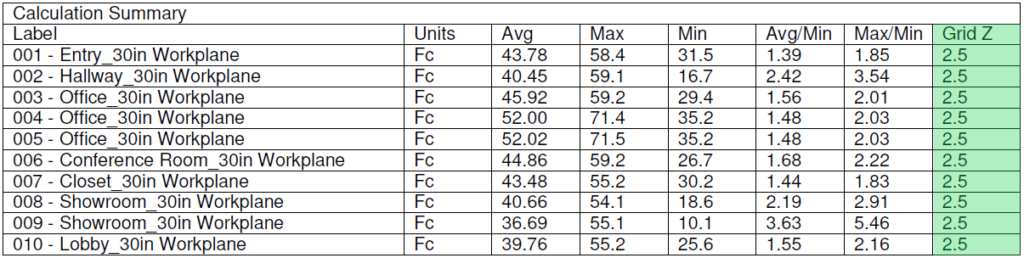
Grid Z shows the distance from the ground to the work-plane, measured in feet.

The Luminaire Schedule compiles all of the raw data from the IES files into a single table. It organizes the various IES files by their labels and is also useful as a lighting legend and a quick reference for quote generation.
Symbol

The symbol is the identifier on the drawing. The color can be changed based upon the luminaire to stand out from similar products, or it can be the same color as the rest to mask placement.
Photometrics can be as colorful or as plain as needed to focus the client's attention upon the details that are required.
Qty – Quantity
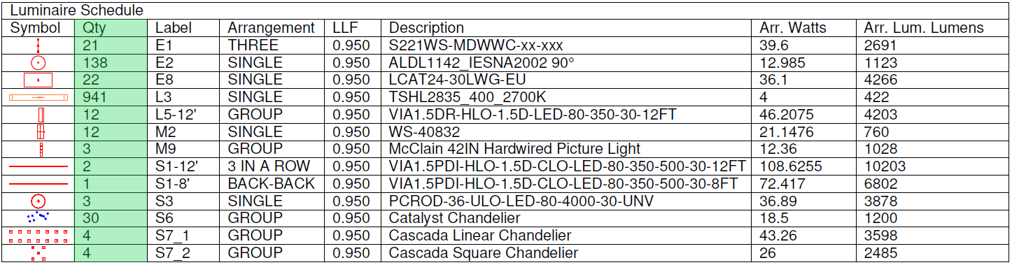
The Quantity is an automatically generated number as each symbol is placed within the drawing. Consider this a perfect Bill of Material. The only human error that could be caused is if extra symbols are added. This error is usually seen with excessive light levels.
This quantity is often used for quick invoice creation.
Label

The label is another identifier. It is usually inserted near the fixture within the plans, but is also a way to organize products in a quick reference fashion.
Generally these labels are provided by the designer. These are usually 1-3 characters in length, but can be longer as needed.
The labels are often A letter which distinguishes a certain fixture type, followed by additional numbers and letters to denote which one of that fixture type is used.
Arrangement
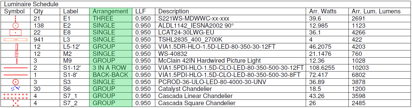
The Arrangement specifies how many of the same IES file and what order they are placed in.
The IES file is usually a single fixture or lamp, while the arrangement can be multiple fixtures in a specific pattern.
Using arrangements helps reduce the clutter within the drawing. Instead of 719 individual labels of rope light as we see in this example, perhaps each run could be shown individually. Remember: with each new length, a new line item is generated within the Luminaire Schedule, which is why the client preferred this approach instead. For other arrangements such as the M8 there are two fixture heads mounted back-to-back. One label instead of two.
Grouping fixtures may allow placement of a fixture that would otherwise not have its own IES file. This is great for chandeliers and other decorative fixtures that are only holders for the lamps. A group of the lamp IES files will be in the schedule as 1 chandelier, instead of 15 B11 lamps.
LLF – Light Loss Factor

The LLF is the Light Loss Factor. This is a percentage of light produced from the fixture. 1.0 is 100% of the light output. Reducing this number can show a derated light which can be from many different environmental factors or manufacturer requirements, including but not limited to dirt, age of the lamp, heat, voltage and more.
In general an LED is usually shown with 0.95 (5% loss) as a conservative estimate of initial fixture performance compared to factory statistics. Even if the light doesn't perform to 100% of the packaging, this 5% provides some "wiggle-room" for estimating purposes.
Lamp and or fixture type may require further depreciation for greater estimate accuracy.
Advanced techniques can be used to determine a more appropriate LLF. These techniques usually require knowledge of operational hours and lifetime operational statistics of the fixture.
Description

The description can be the exact part number used, or it can show a generic description of the product.
Showing the part number may provide greater transparency with the client or the installation team, but a generic description may prevent a client from taking your drawing and shopping around.
(Arr. Watts) – Arrangement Watts

Arrangement Watts are the sum total of all luminaire watts from the whole fixture arrangement. A quick reference of this column shows the total load provided by each arrangement of fixtures.
An example may be you can look at a group of luminaires on a chandelier and determine there are 15 lamps in the arrangement. Each of them is 5 watts, so the total wattage draw from all 15 lamps is 75 watts, OR you could read "75" in this column instead.
(Arr. Lum. Lumens) – Arrangement Luminaire Lumens

Equally valuable is the Arrangement Luminaire Lumens which combines all lamp or fixture lumens in the arrangement under a single number. Any changes to the individual components will affect the fixture as a whole.
An example: If the arrangement is a fixture with 3 lamps at 10 lumen a piece, the sum total of lumen in the Arrangement Luminaire Lumens column will be 30.
The default in most schedules looks at the individual IES file as a singular entity, but these look at the arrangement as a whole.